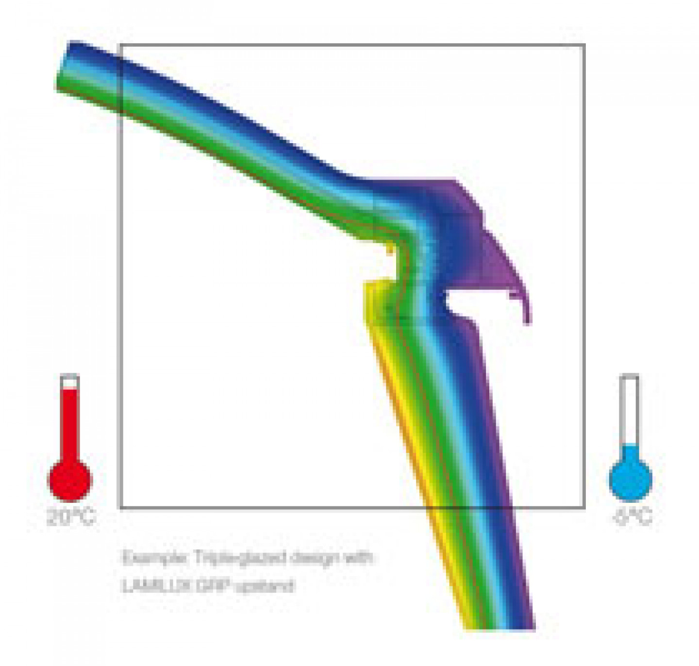
However, colourful charts do not always actually mean anything. To ensure that the diagram is relevant:
- The diagram must clearly state what particular general conditions the calculation were based on.
- The 10° isothermal line, a variable used in building physics must run through the structure as a steady, flawless outline. This is the only way to guarantee that the risk of condensation is minimised under the specified conditions.
Isothermal characteristic of a 10° isothermal line (shown as a continuous red line), in a triple glazed F100 rooflight dome (refer to attached image), under specified boundary conditions. The isothermal line is featured as a steady outline within the structure – the risk of condensation is minimised.
The interaction of energy between individual system components, a crucial factor in determining the Uw value, is clearly visible in isothermal characteristics.
To ensure that the rooflights you are specifying comply with Building Regulations Part L – be sure to ask your rooflight supplier for their Uw values (calculated to EN ISO 10077) and check that any colourful diagrams supplied are actually substantiated by the inclusion of the 10° isothermal line and qualified general conditions.
Inside temperature +20°C, outside temperature -5°. Analytical models for calculating thermal bridges: EN ISO 10211-1, EN ISO 10211-2, EN ISO 10077-2 and EN 13947. Materials: EN ISO 12524, EN ISO 10077-2, EN ISO 6946 and EN ISO 673; Boundary conditions: EN ISO 6946 and EN ISO 10077-2
